Today's efforts in the shed:-
First job was properly mounting the tank - the frame had these pressings in to hold the original tank - so they needed to be cut off..
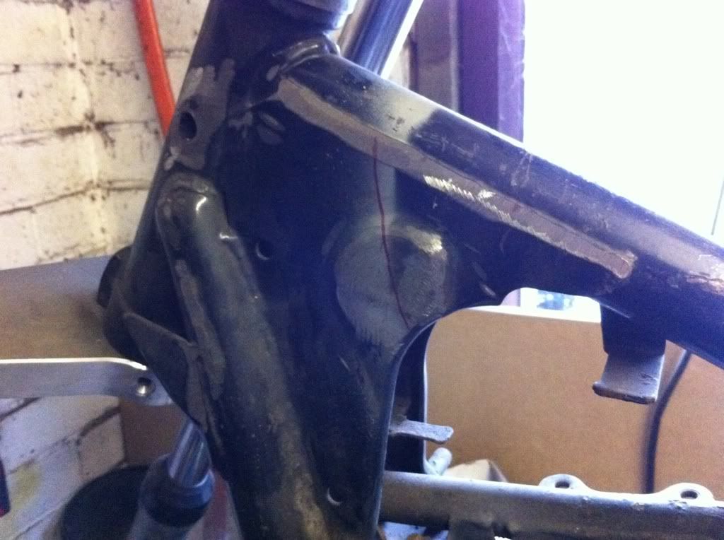
With the engine out it was great to be able to get to the other side of the frame too, decided the best course of action was to cut a section out completely and put a decent piece of plate into fill the void:-
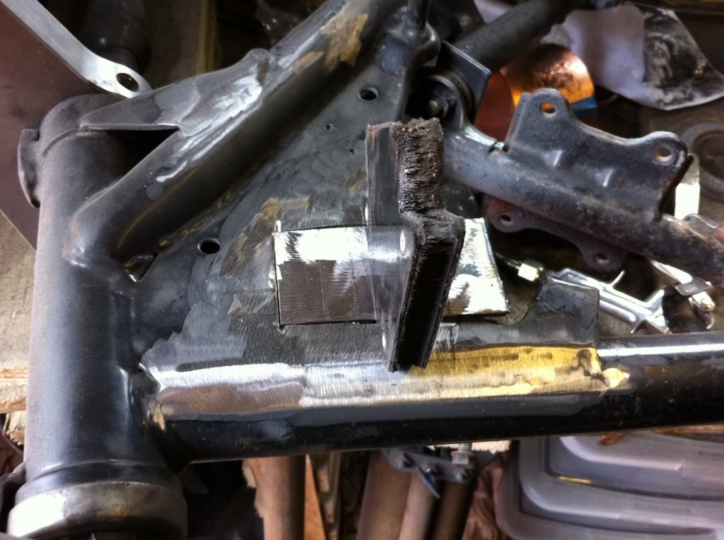
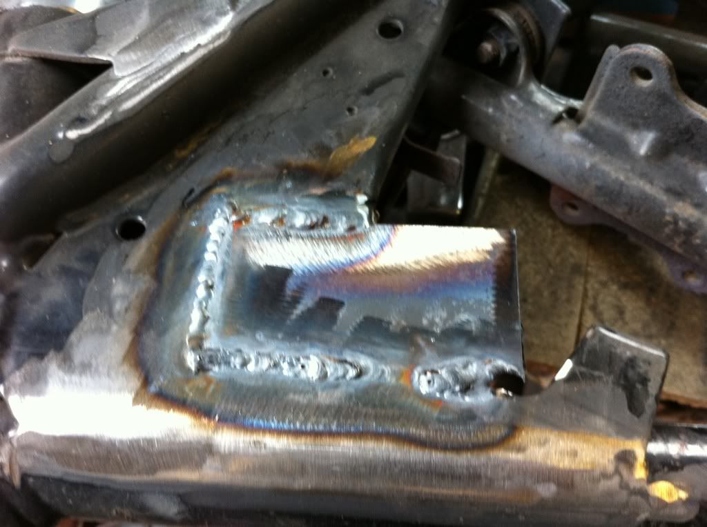
and the other side likewise:-
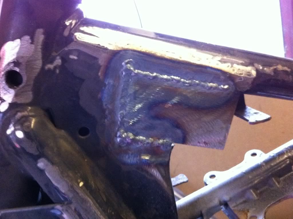
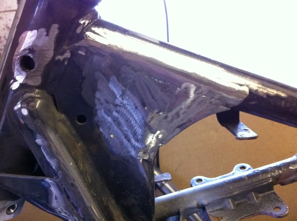
Quickly ground it all back and it was looking pretty good!
Next up - marked out the holes from the tank, drilled the frame and put some threaded inserts in:-
Must have forgotten to take pictures of them welded up, but that’s one ticked off the list!
The shovel / sidecar number plate mount had a chop down as I've gone for a smaller number plate. it looks MUCH better!
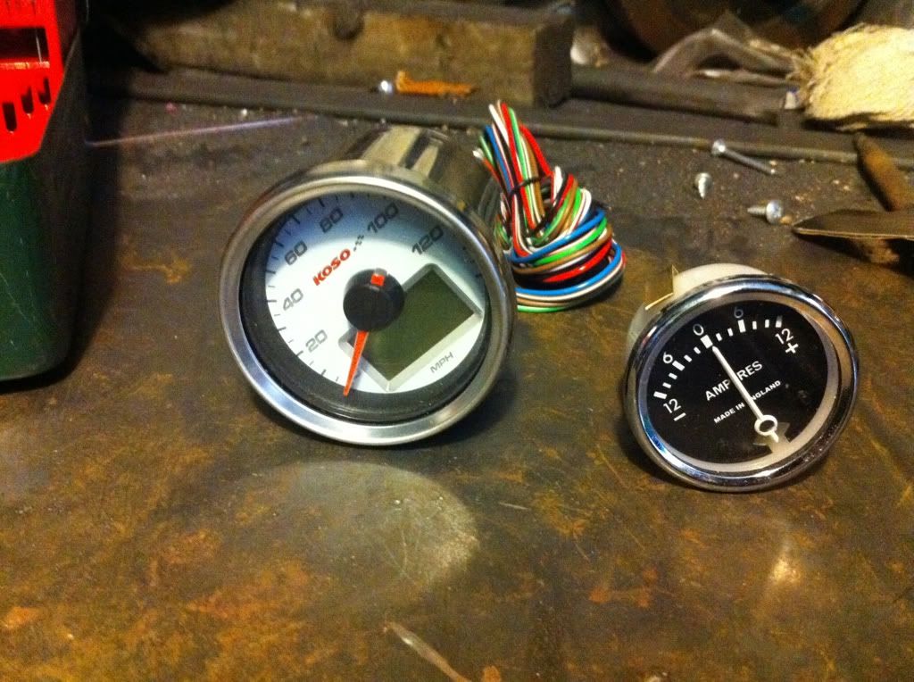
Next up - Speedo mount - I hadn't planned to use an ammeter, but I thought a cluster of controls would look much better. Here are the dials I have. I would like the speedo to be black with white writing, but that'll be one for the future to worry about…
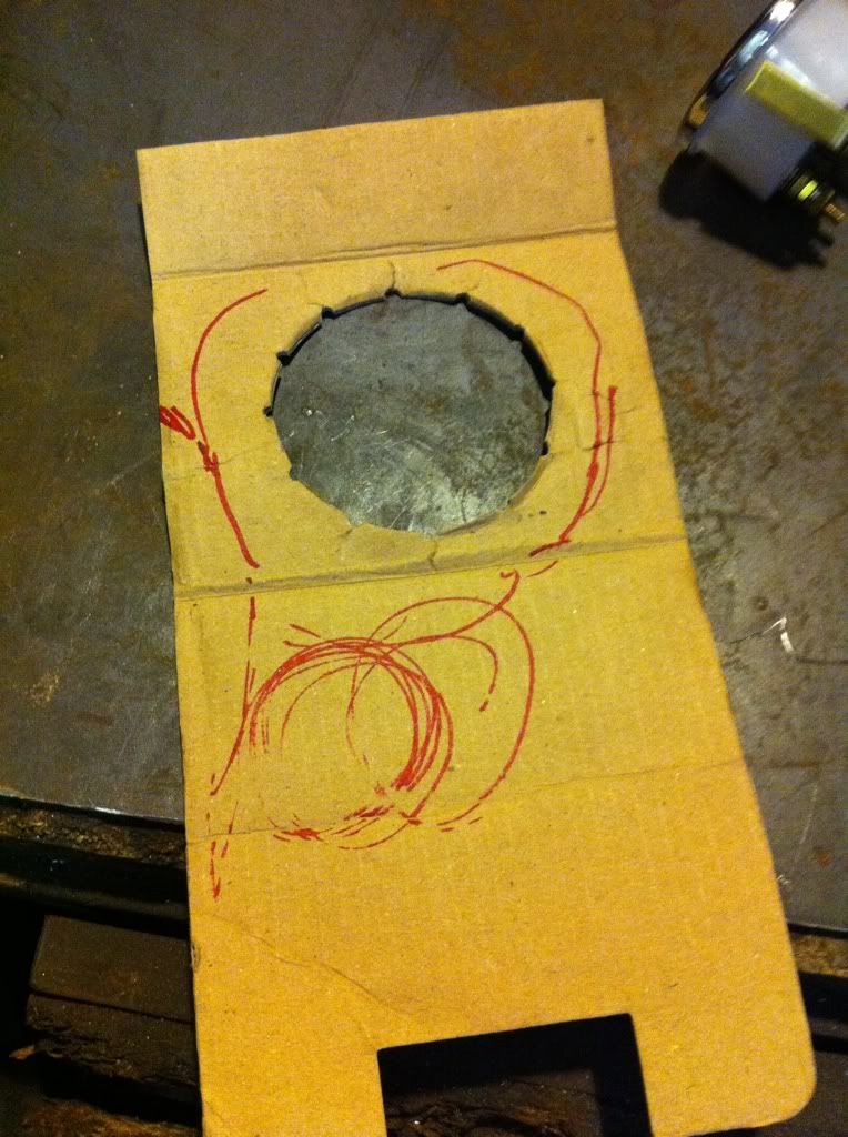
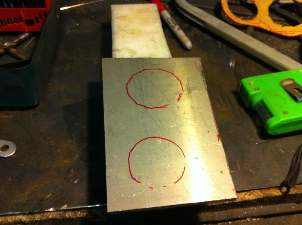
I intent to mount the controls so they are to the right side of the tank, so free sketched the layout of the units onto the insert of the speedo box:-
I tried to take a pic next to the tank, but it didn’t come out properly - but this is (very) roughly the effect I am after….
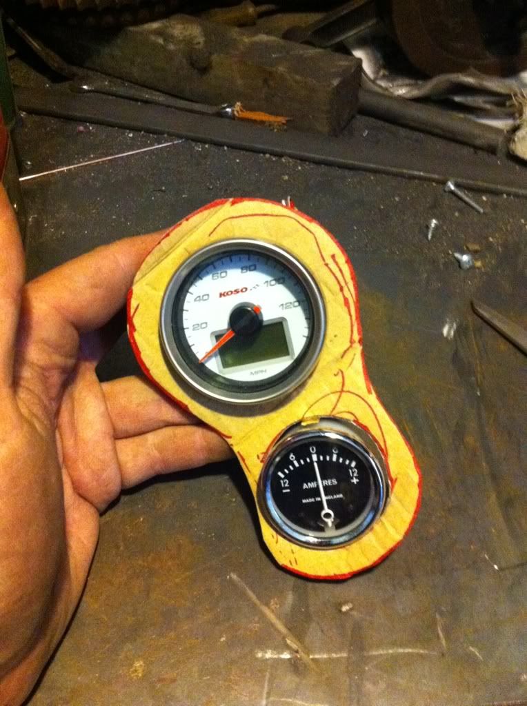
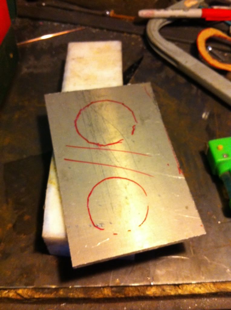
Picked up some 5mm Alloy in Newark a while back, that’s what I'll be using - this is a quick mock up of the dial positions
Instead of a boring flat panel I hope to bend the panel twice, to give a slight stepped effect - I attempted to bend it by hand, but it wasn’t so easy - I figured it would be easier when I had removed some of the waste….
And after a bit of grinding:-
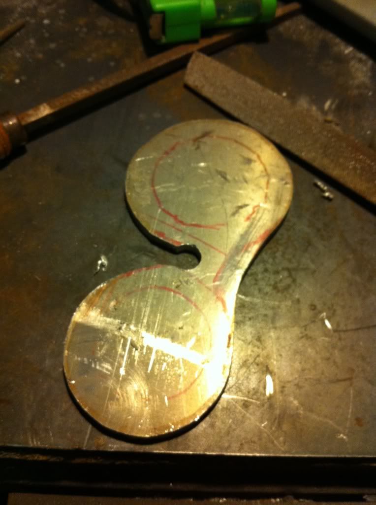
I'll need to have a bit more time sorting these out, and getting the circles more accurate….
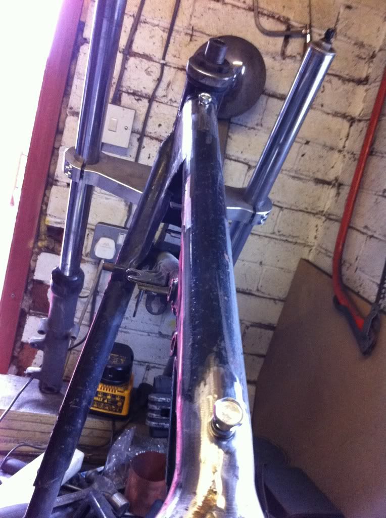
Finally I threaded the front of the yokes to take the headlight mount, as it first went on:-
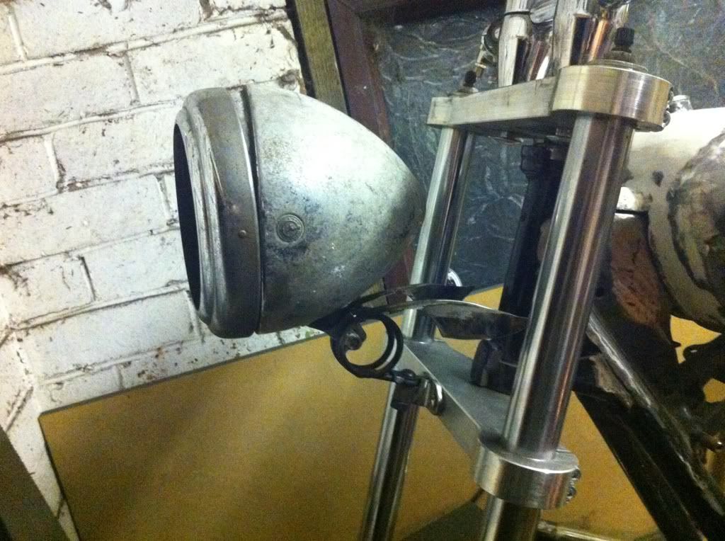
looks good - although it sticks too far forward.
It will need to be more like this:-
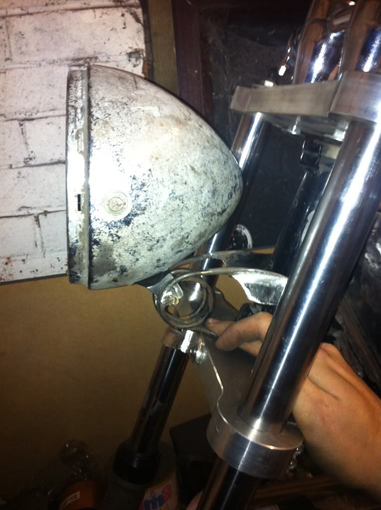
more adaptation required!
Evening all!
haven't had much chance to post over the last couple of weeks - been stupid busy with work. Managed to free up Friday to have a day on the bike - although I had to get back home for 5pm because of plans that evening.
My big nexus in the whole project has been the engine - still now it scares the living bejesus out of me. this is largely inexperience and the fact I don’t like not knowing things. With the hayride only 6 months away I had an offer from Toddy to take my engine to his and completely strip and re-build the lot.
You’re a Star Toddy, even if you allude to the fact that the main reason is that you didn’t want to be there fixing it with me on the way to the hayride.
The engine was loaded into the parts hauler on Thursday night, and Friday morning I was up at the crack of dawn and driving merrily over to Toddy's place.
We had limited time to work on the engine, Toddy already had run his posh Korby Hoover over the place, and the engine was set on its stand in the middle of a nice white sheet.
I'll write the rest of this as honestly as possible - true to form with this build.
I had no appreciation that grinding filings in engines was such a big problem. I see this now - but at the time of first building the top end of the engine myself - let's just say my cleanliness levels were not quite as they should have been. The side covers have been off a number of times, and this is where the bulk of the grindings were - working in such a small shed, cutting, grinding and engine building don’t really go together. I now know this - Toddy didn’t make me feel like an idiot - and I thank him greatly for that - like he said - if you don’t know, you don’t know. Now I've no excuses!
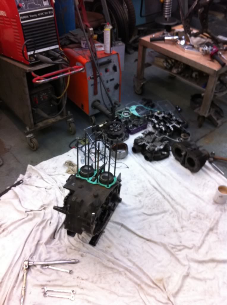
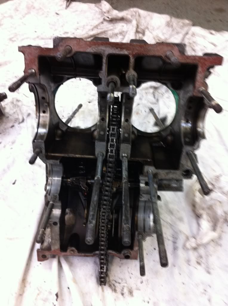
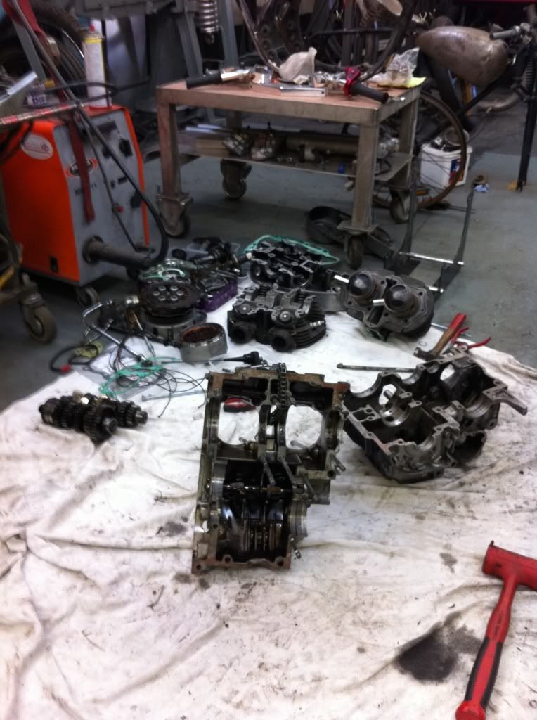
so the engine was stripped down at a rate of knots, the photos are a bit sporadic as we were against the clock. This is the engine stripped to the point I got it last march - everything in the pile at the back needed a good clean, but was in decent fettle.
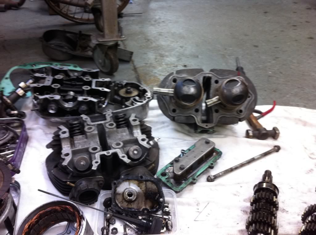
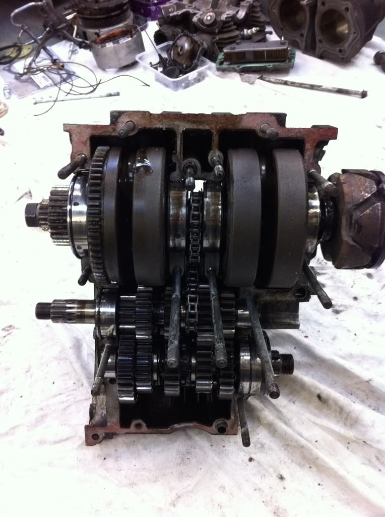
we split the cases with fair amount of ease (well after finding that 1 nut that you always miss) and the bottom end didn’t look too bad. Again Toddy talked me thorough everything in there.
there seemed to be 2 cogs that had crunched something - but there was no major damage to the cogs.
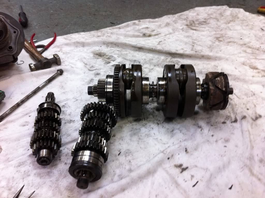
The crank and gears were removed from the bottom casing and set to one side..
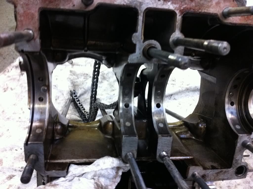
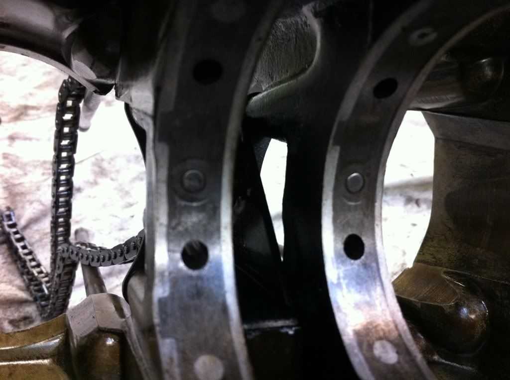
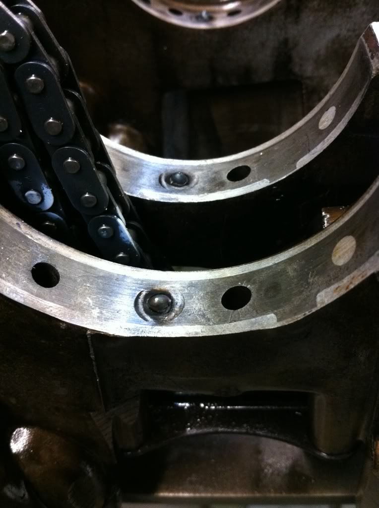
Toddy noticed one problem with the cases that hopefully you will be able to see in the pictures. The crank bearings are located onto a hardened pin which keeps the bearing from spinning, but also the 2 holes either side forces lubrication in the bearing (look at the far left bearing seat). the other 3 had been butchered because the pin had been punched into the casing! there must have been a fair old bit of force used.
Here you go - a closer look. you can see the marks left from the punch…..
Cuppa tea to think about it…….
Toddy suggested welding a bar to the pin to allow us to pull it out…
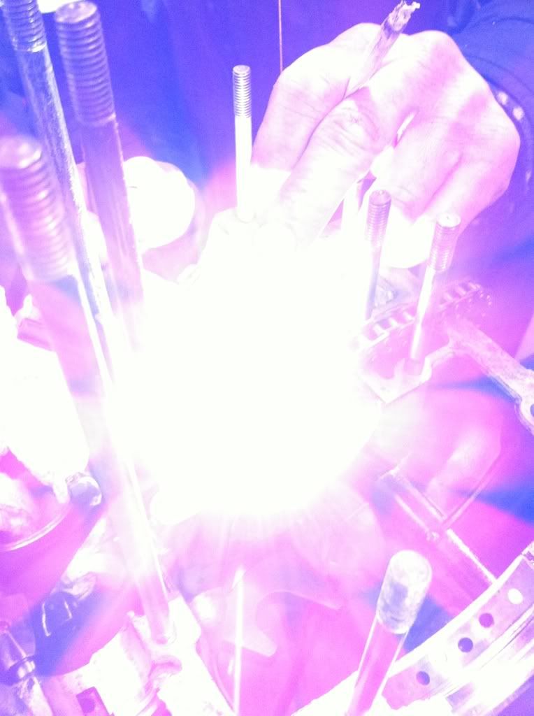
Love this photo - looks like toddy is giving me the finger, but welding so precisely and being able to hold that fag is an art form!
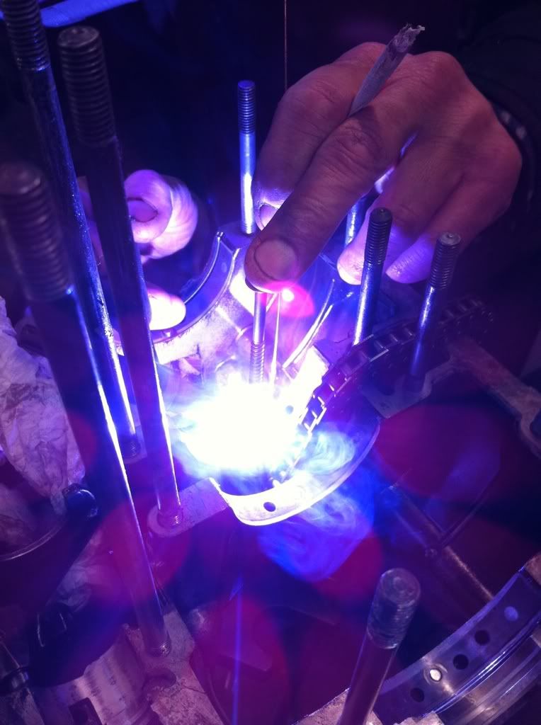
After a few attempts failing it was suggested that we weld a little lug onto the metal pin - after all they are only there to locate the bearings….
Out with the parts cleaner, and plenty of elbow grease and Mr Muscle and we started to reassemble the engine
Bottom end all in, pistons on…
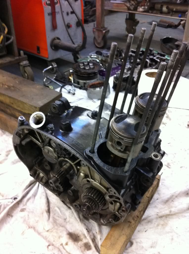
Put the barrels on, and found I was a part missing for the clutch
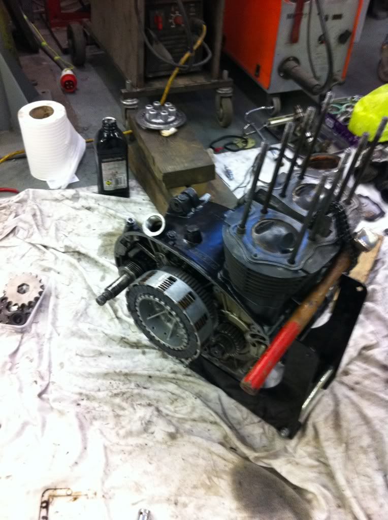
and that is where we had to leave it for the day - I'd 30 mins to get home - 85 miles away!!!
I was slightly bollock'd when I got back!
I will be going back over soon to finish off the head including looking at the valves etc…
A massive thank you to Toddy - your patience is a blessing mate!
Had one of those days today - everything seems to have fucked up at one stage or another. Today has been the first day where I REALLY needed a metal lathe to make all those little bits and bobs...
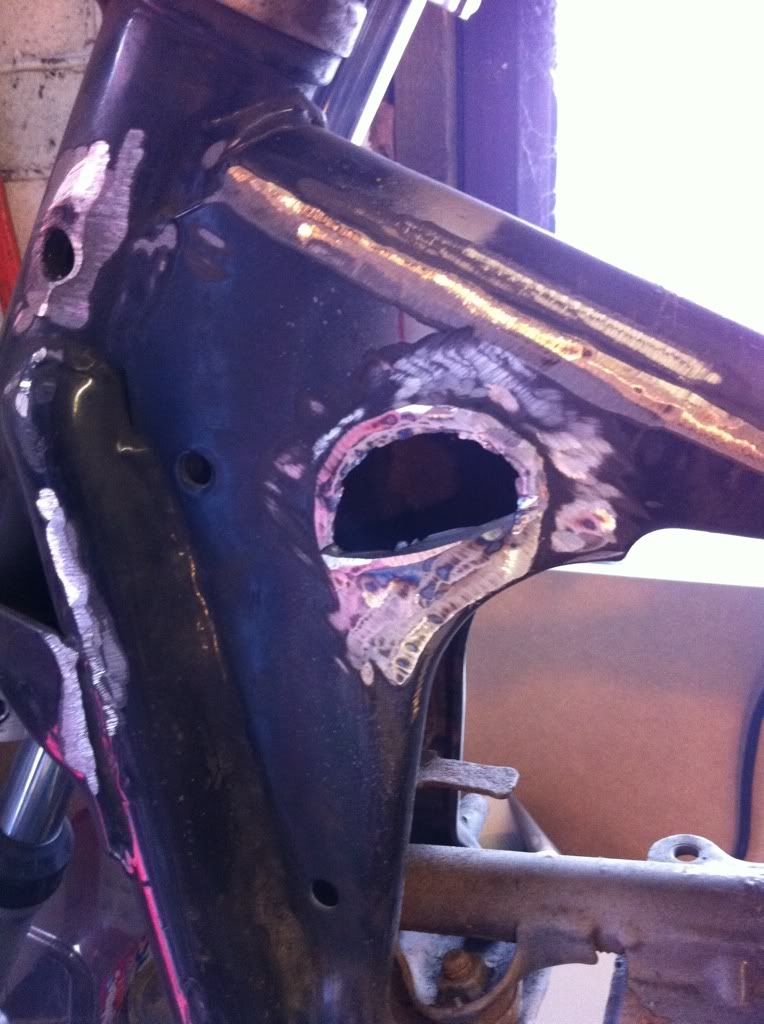
Tidy'd up the weld around the ignition, tried to nitromores the paint, but it wasnt having any of it - so I had to grind it back with a flapper disc, ground out the hole and test fitted the ignition...
Made a plate for the inside of the tank to hold the Thermic Breakers. I made the little spacers with metal in the pillar drill and the angle grinder (not advised) as they will be tucked right in the tank i didnt mind too much. Drilled 2 holes for the spacers, and 3 for the breaker holders to be pop riveted to...
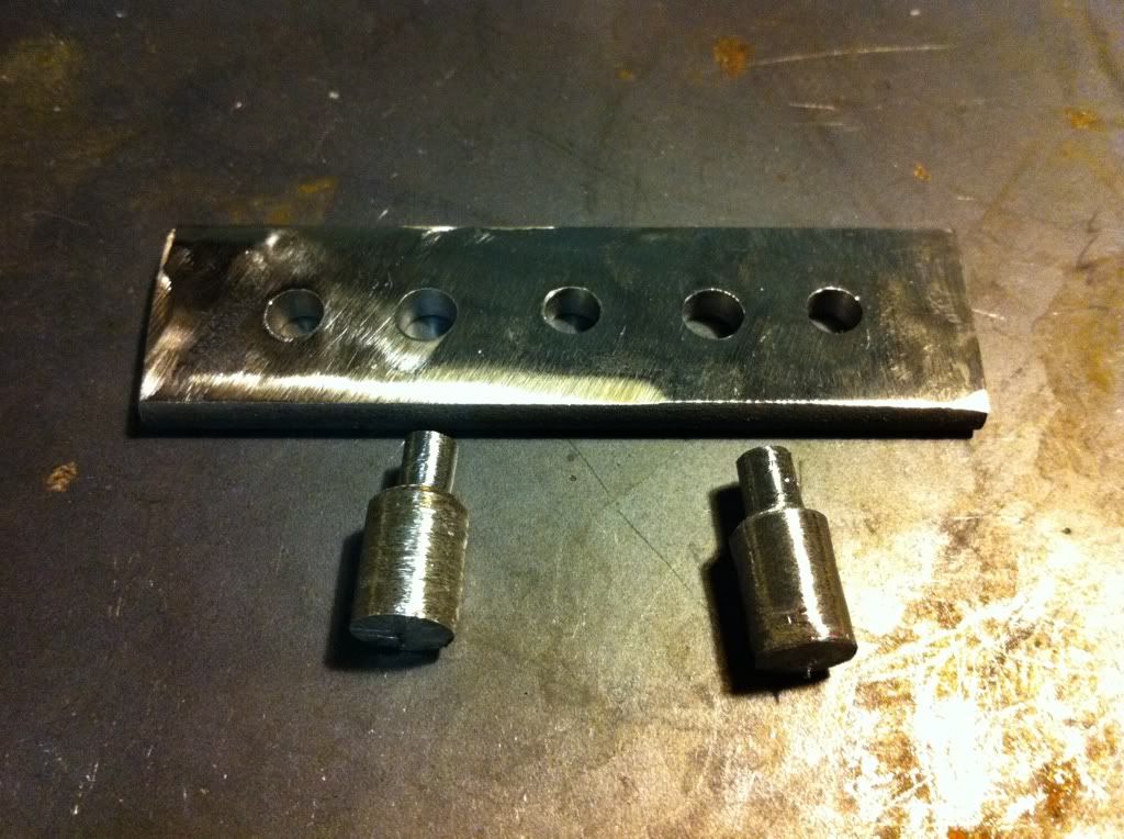
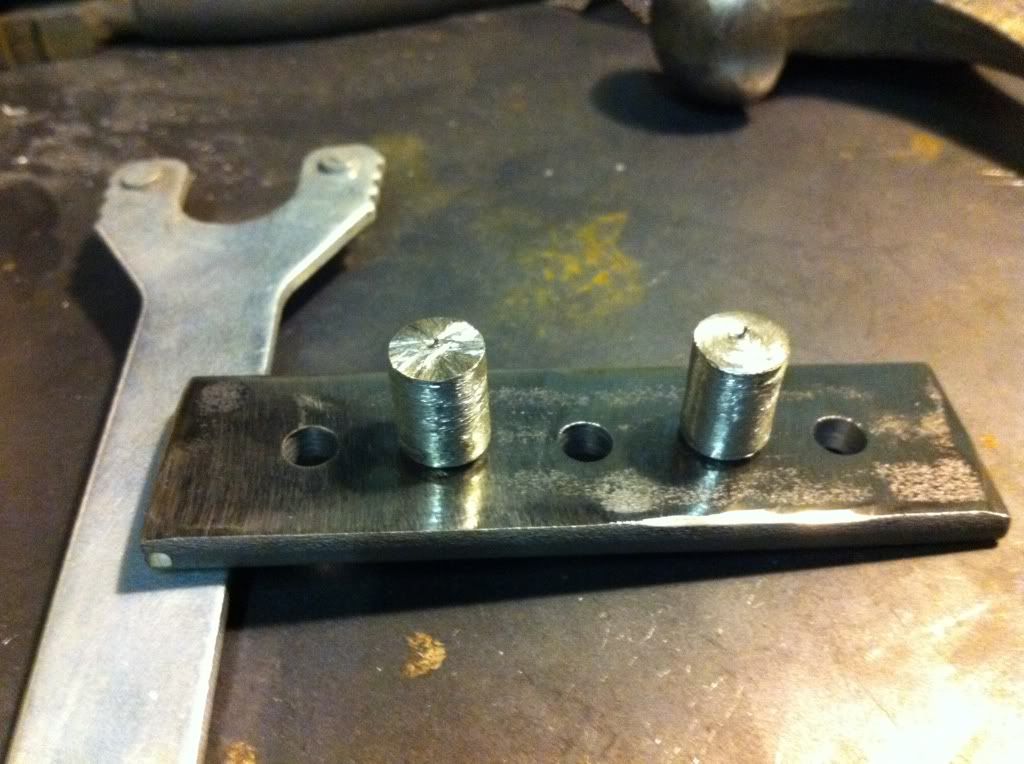

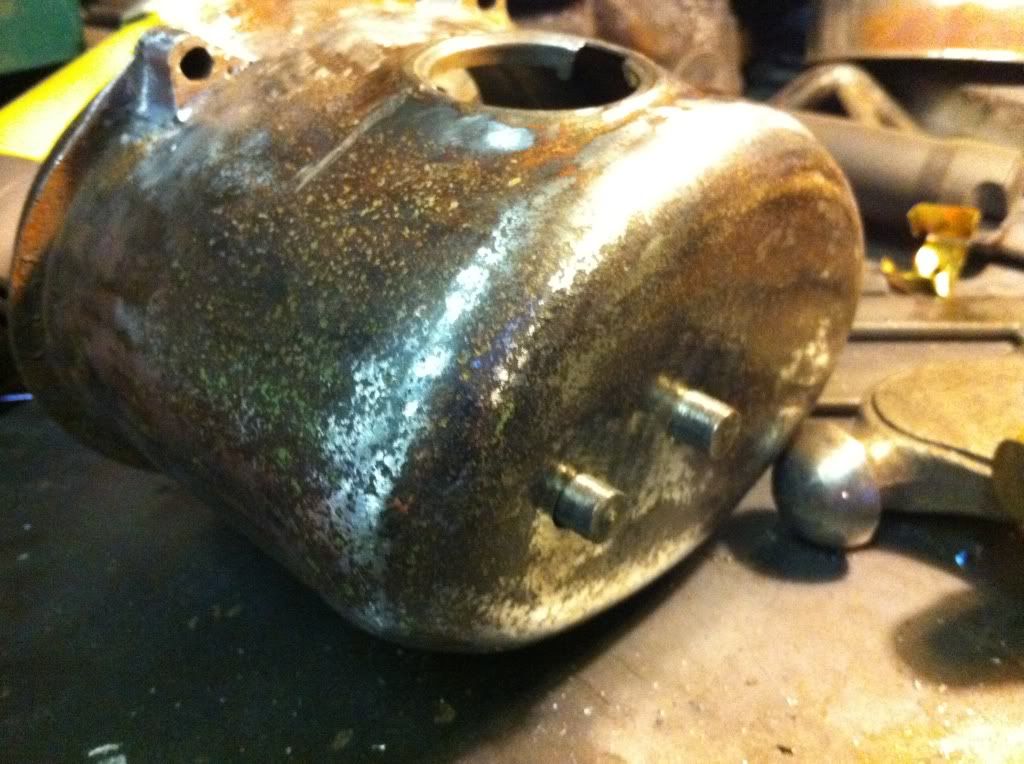
With them welded up, I drilled 2 holes through the tank and welded the spacers from the outside of the tank..
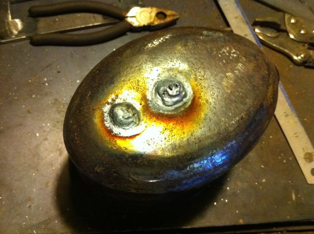
Ground the outside back and it was like the holes were never there!
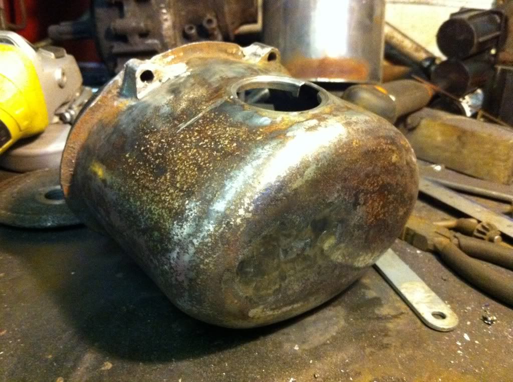
The tank had a quick spray with some black paint to see what it was looking like, pretty cool!
Also made a bit of a tray to strap the batterys too - its longer to stop the batterys clattering against the breakers and the ignition...

Went to fit the breaker holders and realised that my pop riviter wouldnt get in there! BOLLOCKS!
Is there another typre of riviter that I could use??
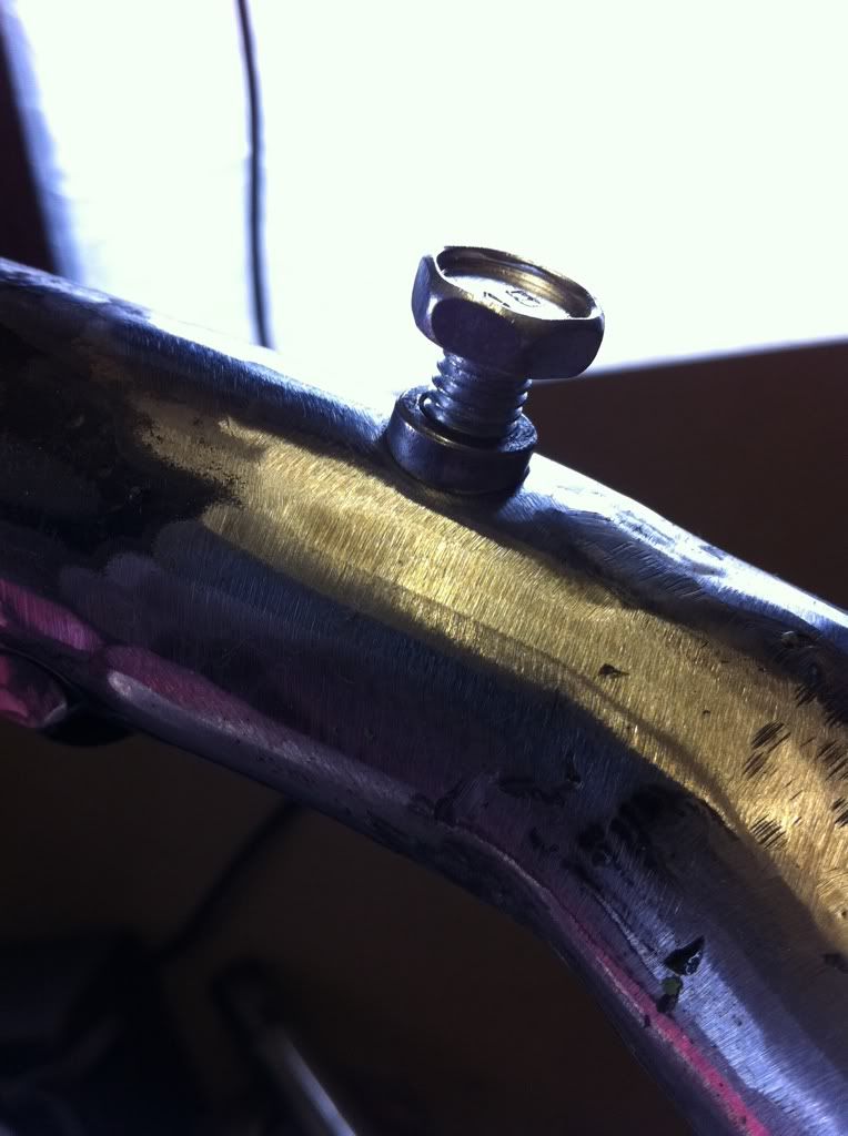
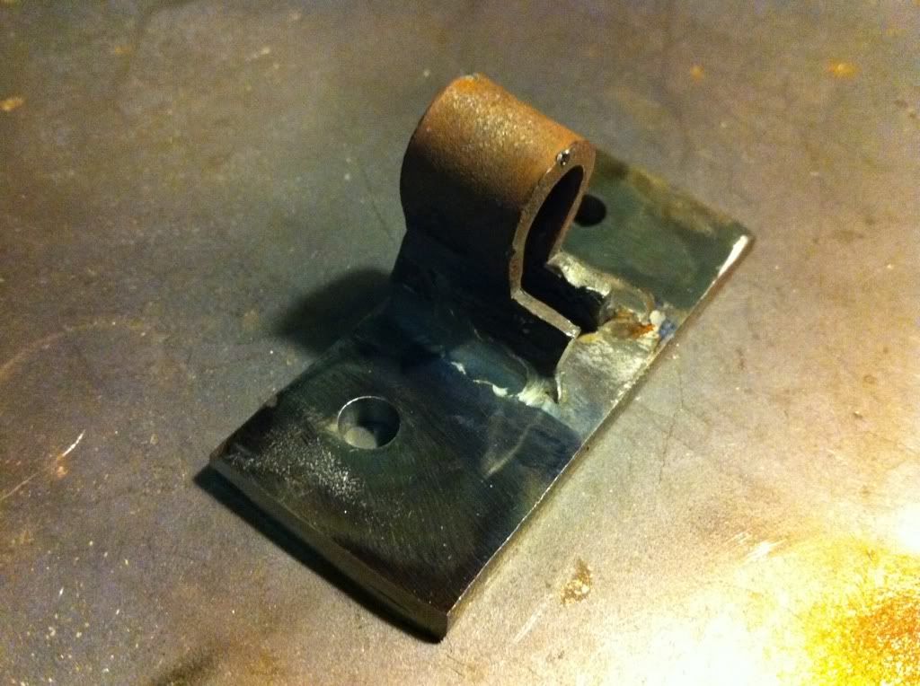
I also spent about an hour making a threaded lug for the headlamp mount, then welding it in place.
Ive come to realise a few things today - My shed is bloody tiny, sitting on a plank of wood which is zip tied to a bas bottle gives you a numb ass and bad back, all of my drill bits are made of cheese and are shit, and I need a metal lathe big time!
Evening all!
Right I've had a good couple of nudges to pull my socks up with the bike - keep my eye on the prize and all that - the hayride is just 6 months away, and I NEED to have it running, and reliable by then!
Had a great day in the shed today, and got a stack done (prepare yourself for a mammoth post!!!)
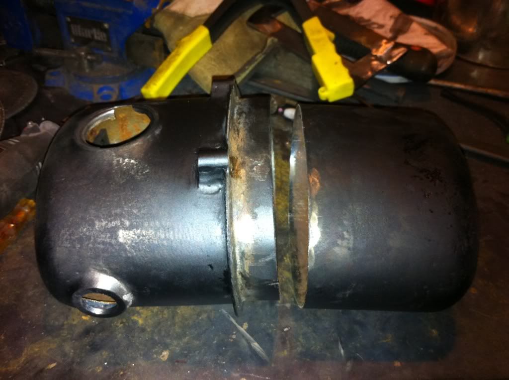
First Job - petrol tank.
I'd already blanked the end off, and was on the hunt for some tube to use to make a fake tunnel. I managed to nick some from dad when I was back down there last weekend.
Cut the tube to the right length and width - it had to be tapered to the back to allow it to fit well:-


Welded it up good and proper each end and neatened the edges up with the grinder.
There was some filling needed on the tank, so I mixed up a golf ball size lump of filler and coated the areas that needed it…
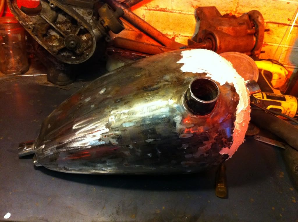
a bit of drying time and then attacked it with the flapper disc to neaten it all off…..
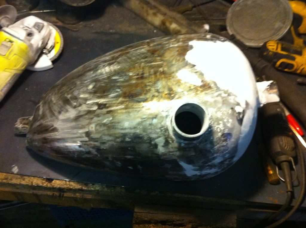
had to leave that for the day - the frame needs a slight modification for it to fit on properly Ithe old tank mounted on to raised sections that need to be ground back). the engine will be coming out (probably tomorrow) so I'll do it when the engine is out…
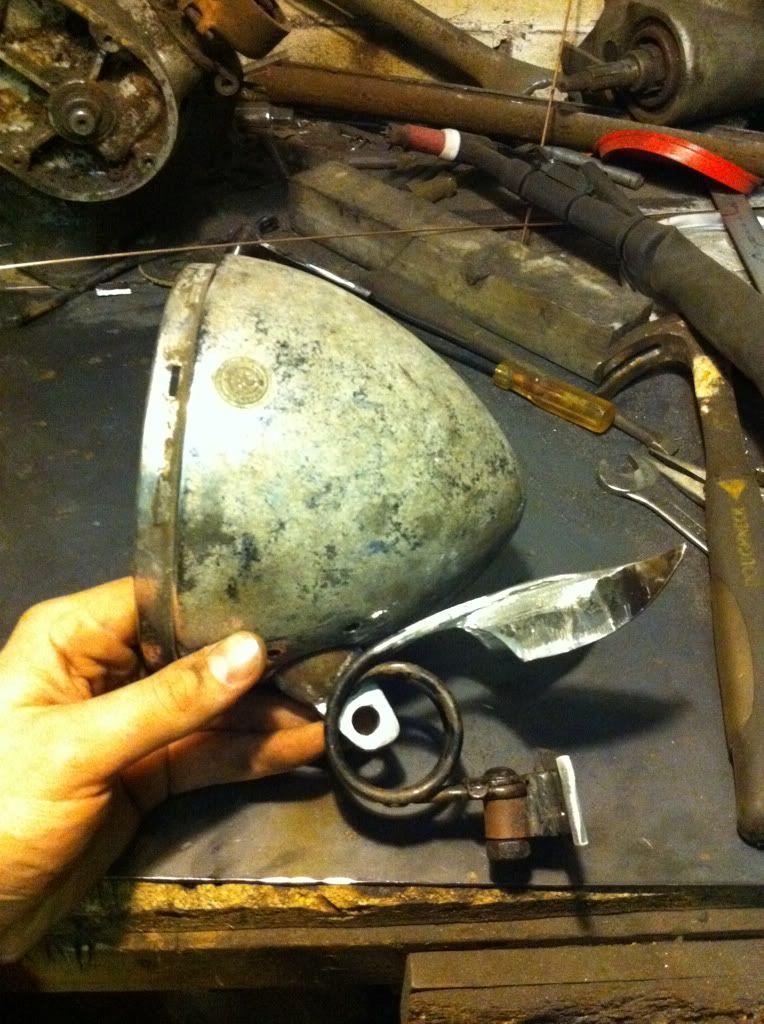
That lead me back to the list - next job - sort the bloody headlamp light out. I have made about 4-5 different mounts for this so far, and have been dissatisfied with each one.
I had a chat with toddy yesterday - and we were saying where the best ideas come from - well for me while I'm sleeping! remembered I had the front off the old saddle kicking about -
Perfect - just what I needed!
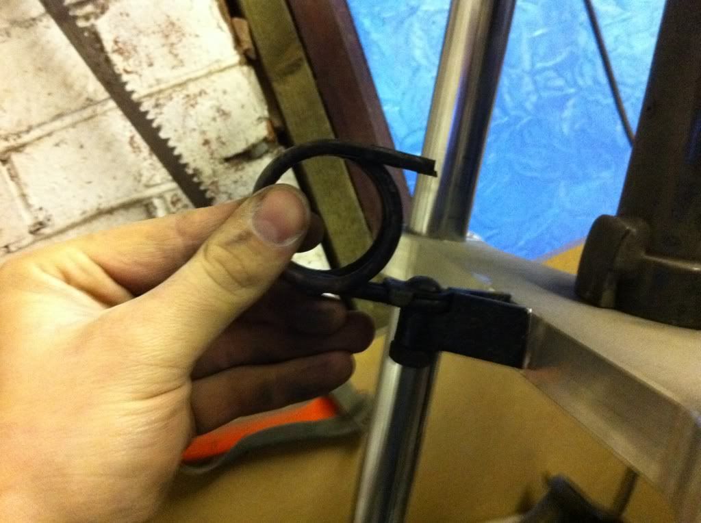
There was already a bolt on mount that could be adapted, and the circles were just what I wanted! Now you may be thinking - why a sprung headlight - that’s never gonna work….
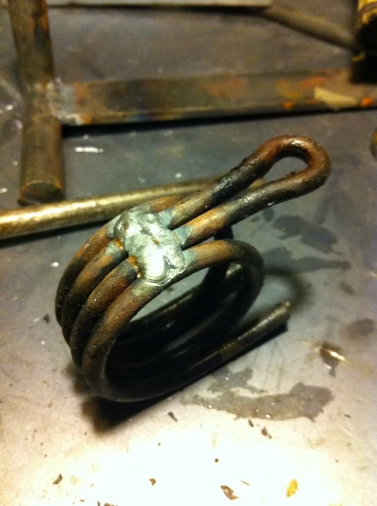
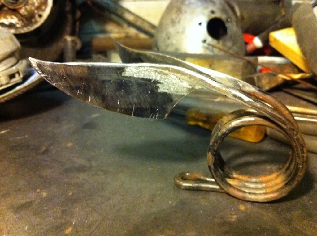
well I ground back the bottom and welded the coils together to make it much stronger
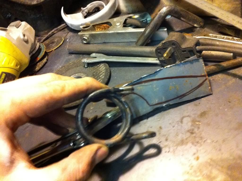
In my vision I wanted something a bit art deco inspired. I loved what toddy has done with his mount - so this is kinda homage to you sir - just with a TC twist!
Sharpied up some cool wing like shapes onto some steel:-
Ground them out (2 pieces back to back held with mole grips when ground so I had a matching pair), and then welded them in place with some extra filler:-
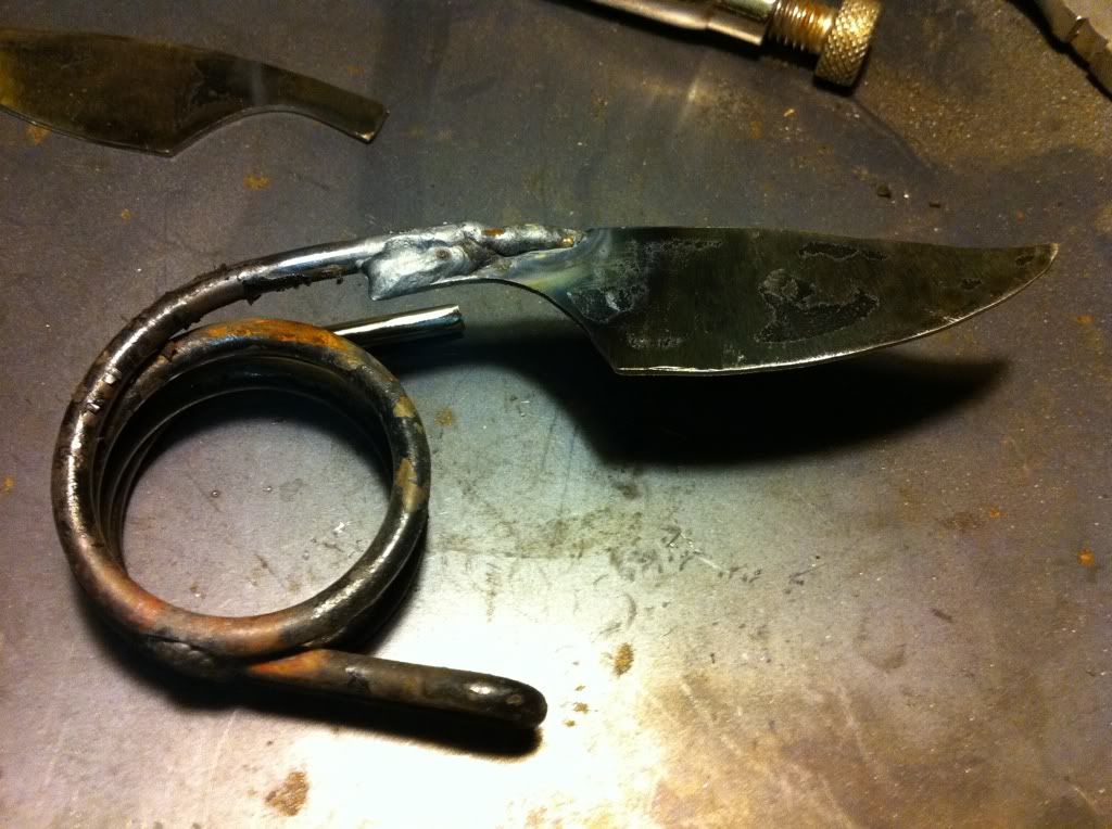
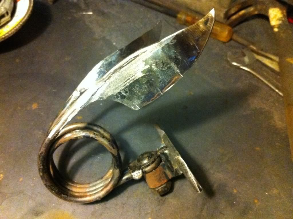
Plenty of grinding and filing later and check these bad boys out!!!!!
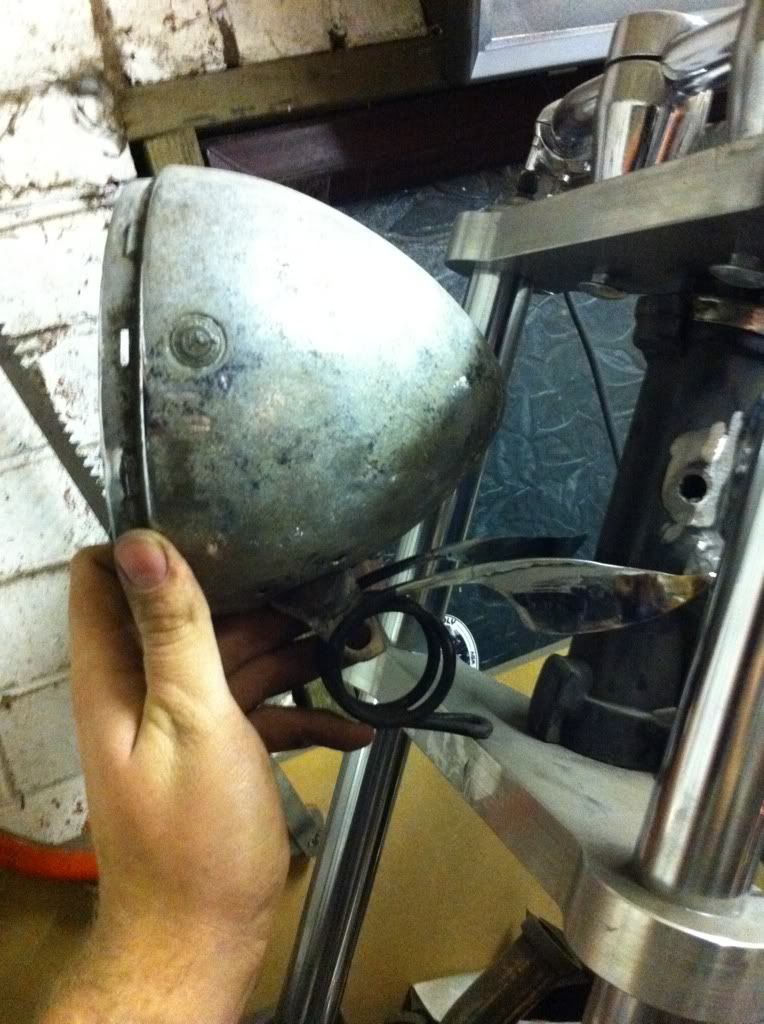
Attempted a bit of a mock up of the lamp and the new mount, and it's looking bloody lovely!
As for mounting it to the yokes, I cut back the old mount, and welded it onto a plate that can be bolted into the yokes. this needs a bit more time tidying up the shape, but it works well!
All bolted together:-
And with the headlamp in situ……
I will need to make some lugs to weld to the inside of the coil to attach the light to, but all good for the now!
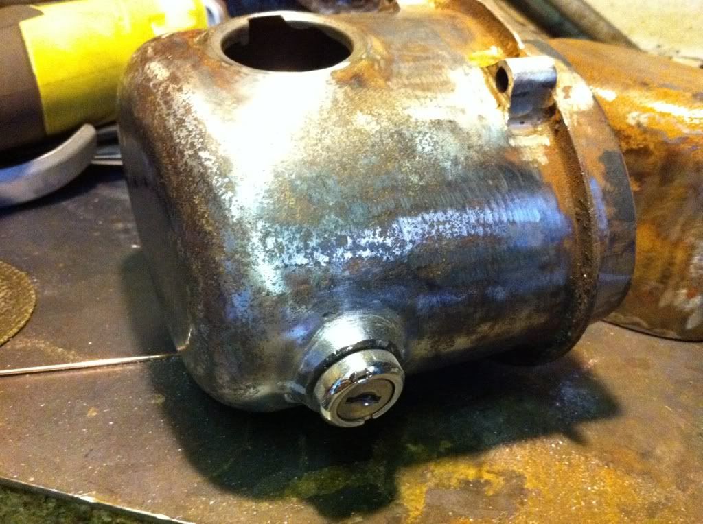
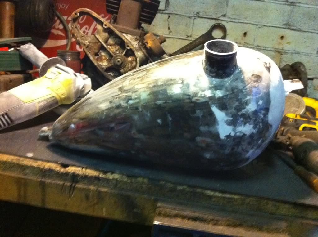
Final job - the ignition switch for the fakey oil tank:-
I've decided to mount the ignition on the back of the tank, so it's out of sight and I'm not buggering about with the Jap cap….
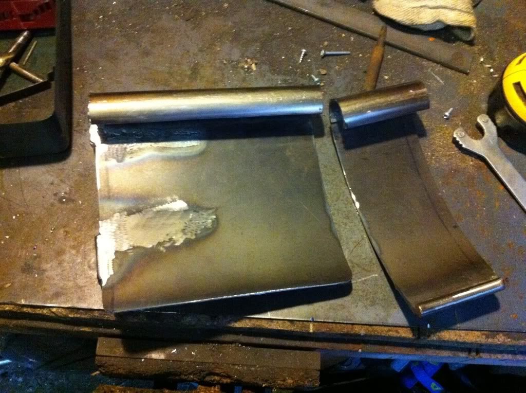
I welded some 5mm sheet to a piece of old tube
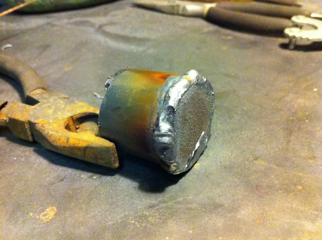
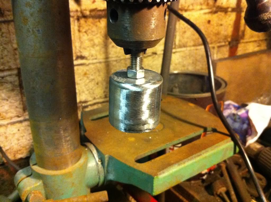
I roughly sorted the welds out with a flapper disc, but it was still a bit shaky, so I drilled a hole in the end, attached it to a nut and bolt and put it I the pillar drill:-
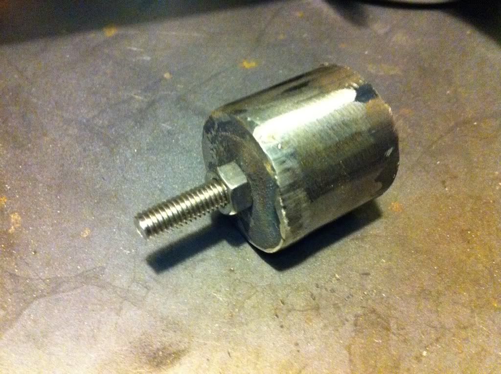
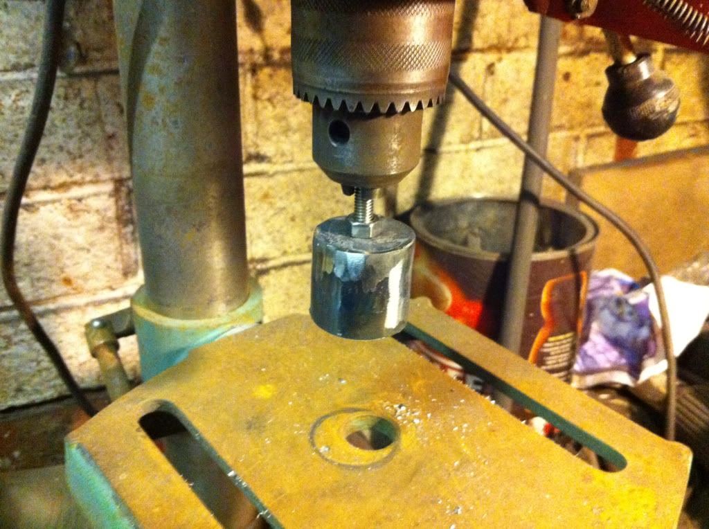
turned the pillar drill on and used a flapper disk to get it shaped nicely:-
Drilled a hole in the side of the tank and widened it (badly) with a die grinder bit in a hand drill:-
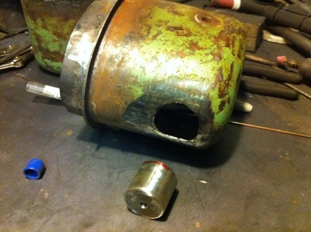
I consciously didn’t widen the hole for the ignition switch, as I didn’t want it all to warp with the heat of welding it. It was a right twat to weld as the steel wasn’t so thick in places, but it’s a half decent job….
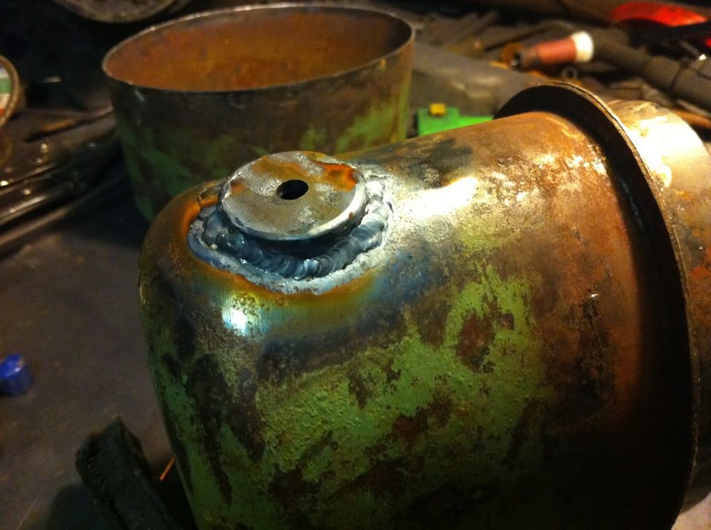
and there it was left for the day. not a bad effort in my eyes!
still got a load to do, but I'm going to be hitting that to do list in a serious way the next couple of weeks!